




Features
WFD6R80F-ECL47
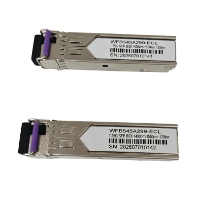
The 10G CWDM SFP+ 80km LC SMF transceiver delivers 80km reach over single-mode fiber with eight wavelength options from 1470nm to 1610nm. Built with an EML transmitter and APD receiver, it ensures reliable signal integrity across long distances. The standard SFP+ LC interface is hot-swappable and fully MSA-compliant with DDM support for real-time network monitoring. It is an ideal solution for metro networks and long-haul links where fiber capacity needs to be maximized.
The 10G CWDM SFP+ 80km LC SMF transceiver delivers exceptional speed with support for data rates up to 11.3Gbps, powering through demanding tasks like high-definition video, cloud services, and large data transfers without a hitch. This high bandwidth ensures your network stays responsive even during peak usage, so your users experience smooth, uninterrupted performance every time. Built to handle the most data-intensive applications with ease, this transceiver gives your network the headroom it needs to grow.
Covers distances up to 80 kilometers over standard single-mode fiber, making it easy to connect remote sites and regional offices without extra equipment. This long reach saves you from buying costly signal boosters or repeaters, simplifying your network design and keeping your budget in check. Trust your data to travel the full distance with clarity and strength, from one end to the other.
The 10G CWDM SFP+ 80km LC SMF transceiver runs on a single +3.3V power supply, making integration simple and trouble-free. This low-power design keeps heat generation to a minimum, improving overall system reliability and longevity. Choose a smarter, cooler-running solution that saves energy and reduces operating costs. You get strong performance without putting extra strain on your existing power infrastructure. It is a practical, cost-effective choice that helps you build a greener, more efficient network.
The 10G CWDM SFP+ 80km LC SMF transceiver made with environmentally safe materials and fully RoHS-6 compliant, this transceiver helps you meet global green standards with ease. By choosing this module, you are supporting a cleaner planet while ensuring your network equipment is built with safer components. It is responsible, reliable, and ready for deployment in any eco-conscious environment.
Parameter
|
Absolute Maximum Ratings |
|||||||||||||||
|
Parameter |
Symbol |
Min. |
Max. |
Unit |
Note |
||||||||||
|
Storage Temperature |
Tst |
-40 |
85 |
°C |
|||||||||||
|
Input Voltage |
Vin |
GND |
Vcc |
V |
|||||||||||
|
Power Supply Voltage |
Vcc-Vee |
-0.5 |
+3.6 |
V |
|||||||||||
|
Recommended Operating Conditions |
|||||||||||||||
|
Parameter |
Symbol |
Min. |
Typical |
Max. |
Unit |
Note |
|||||||||
|
Power Supply Voltage |
Vcc |
3.135 |
3.3 |
3.465 |
V |
- |
|||||||||
|
Operating Case Temperature |
Tc |
0 |
- |
70 |
°C |
- |
|||||||||
|
Data Rate |
DR |
- |
10.3125 |
11.3 |
Gbps |
- |
|||||||||
|
Total Supply Current |
- |
- |
- |
450 |
mA |
- |
|||||||||
|
Electrical-Optical Specification |
|||||||||||||||
|
Transmitter |
|||||||||||||||
|
Parameter |
Symbol |
Min. |
Typ. |
Max. |
Unit |
Note |
|||||||||
|
Optical Central Wavelength |
l |
lp-6.5 |
lp |
lp+6.5 |
nm |
1 |
|||||||||
|
Optical Spectral Width (-20dB) |
Dl |
1 |
nm |
||||||||||||
|
Side Mode Suppression Ratio |
SMSR |
30 |
dB |
||||||||||||
|
Average Optical Output Power |
Po |
0 |
+4 |
dBm |
2 |
||||||||||
|
Extinction Ratio |
Er |
9 |
dB |
||||||||||||
|
Average Power of disable Transmitter |
-45 |
dBm |
|||||||||||||
|
Relative Intensity Noise |
RIN |
-128 |
dB/Hz |
||||||||||||
|
Optical return loss tolerance |
-12 |
dB |
|||||||||||||
|
Output Eye |
Compliant with IEEE802.3ae |
3 |
|||||||||||||
|
Optical- Electrical Specification |
|||||||||||||||
|
Receiver |
|||||||||||||||
|
Parameter |
Symbol |
Min. |
Typ. |
Max. |
Unit |
Note |
|||||||||
|
Operate Wavelength |
l |
1460 |
1621 |
nm |
|||||||||||
|
Sensitivity |
Pr |
-23 |
dBm |
4 |
|||||||||||
|
Saturation |
Ps |
-7 |
dBm |
4 |
|||||||||||
|
LOS De-assert Level |
-25 |
dBm |
|||||||||||||
|
LOS Assert Level |
-35 |
dBm |
|||||||||||||
|
LOS Hysteresis |
0.5 |
5.0 |
dB |
||||||||||||
Note:
1. λp =The peak wavelength (1471, 1491, 1511, 1531, 1551, 1571, 1591, 1611)
2. The optical power is Coupled into SMF.
3. Measured with a PRBS 231-1 test pattern @10.3125Gbps.
4. Measured with a PRBS 231-1 test pattern @10.3125Gbps, BER ≤1×10-12 and including back to back.
|
Electrical Characteristics |
|||||||
|
Parameter |
Symbol |
Min. |
Typical |
Max. |
Unit |
Note |
|
|
SDA / SCL |
VH |
2 |
Vcc |
V |
|||
|
VL |
0 |
0.8 |
V |
||||
|
Transmitter |
|||||||
|
Input Differential Impedance |
Zin |
90 |
100 |
110 |
Ω |
- |
|
|
Data Input Swing Differential |
Vin |
100 |
1200 |
mV |
|||
|
TX Disable |
Disable |
2.0 |
Vcc |
V |
|||
|
Enable |
0 |
0.8 |
V |
||||
|
TX Fault |
Fault |
2.0 |
Vcc |
V |
|||
|
Normal |
0 |
0.8 |
V |
||||
|
Receiver |
|||||||
|
Output Differential Impedance |
Zout |
90 |
100 |
110 |
Ω |
||
|
Data Output Swing Differential |
Vout |
350 |
900 |
mV |
|||
|
LOS |
High |
2.0 |
Vcc |
V |
|||
|
Low |
0 |
0.8 |
V |
||||
PIN Description
|
Pin |
Signal Name |
Description |
Plug Seq. |
Notes |
|
1 |
VEET |
Transmitter Ground |
1 |
|
|
2 |
TX FAULT |
Transmitter Fault Indication |
3 |
Note 1 |
|
3 |
TX DISABLE |
Transmitter Disable |
3 |
Note 2 |
|
4 |
SDA |
SDA Serial Data Signal |
3 |
|
|
5 |
SCL |
SCL Serial Clock Signal |
3 |
|
|
6 |
MOD_ABS |
Module Absent. Grounded within the module |
3 |
|
|
7 |
RS0 |
Not Connected |
3 |
|
|
8 |
LOS |
Loss of Signal |
3 |
Note 3 |
|
9 |
RS1 |
Not Connected |
3 |
|
|
10 |
VEER |
Receiver ground |
1 |
|
|
11 |
VEER |
Receiver ground |
1 |
|
|
12 |
RD- |
Inv. Received Data Out |
3 |
Note 4 |
|
13 |
RD+ |
Received Data Out |
3 |
Note 4 |
|
14 |
VEER |
Receiver ground |
1 |
|
|
15 |
VCCR |
Receiver Power Supply |
2 |
|
|
16 |
VCCT |
Transmitter Power Supply |
2 |
|
|
17 |
VEET |
Transmitter Ground |
1 |
|
|
18 |
TD+ |
Transmit Data In |
3 |
Note 5 |
|
19 |
TD- |
Inv. Transmit Data In |
3 |
Note 5 |
|
20 |
VEET |
Transmitter Ground |
1 |
Notes:
Plug Seq.: Pin engagement sequence during hot plugging.
1) TX Fault is an open collector output, which should be pulled up with a 4.7k~10kΩ resistor on the host board to a voltage between 2.0V and Vcc+0.3V. Logic 0 indicates normal operation; Logic 1 indicates a laser fault of some kind. In the low state, the output will be pulled to less than 0.8V.
2) Laser output disabled on TDIS >2.0V or open, enabled on TDIS <0.8V.
3) LOS is open collector output. Should be pulled up with 4.7k~10kΩ on host board to a voltage between 2.0V and 3.6V. Logic 0 indicates normal operation; logic 1 indicates loss of signal.
4) RD-/+: These are the differential receiver outputs. They are internally AC-coupled 100 differential lines which should be terminated with 100Ω (differential) at the user SERDES.
5) TD-/+: These are the differential transmitter inputs. They are internally AC-coupled, differential lines with 100Ω differential termination inside the module.
Order Information
|
Part Number |
Product Description |
|
WFD6R80F-ECL47 |
CWDM 1471 EML, 10Gbps, LC, 80km, 0℃ ~ +70℃, with DDM |
|
WFD6R80F-ECL49 |
CWDM 1491 EML, 10Gbps, LC, 80km, 0℃ ~ +70℃, with DDM |
|
WFD6R80F-ECL51 |
CWDM 1511 EML, 10Gbps, LC, 80km, 0℃ ~ +70℃, with DDM |
|
WFD6R80F-ECL53 |
CWDM 1531 EML, 10Gbps, LC, 80km, 0℃ ~ +70℃, with DDM |
|
WFD6R80F-ECL55 |
CWDM 1551 EML, 10Gbps, LC, 80km, 0℃ ~ +70℃, with DDM |
|
WFD6R80F-ECL57 |
CWDM 1571 EML, 10Gbps, LC, 80km, 0℃ ~ +70℃, with DDM |
|
WFD6R80F-ECL59 |
CWDM 1591 EML, 10Gbps, LC, 80km, 0℃ ~ +70℃, with DDM |
|
WFD6R80F-ECL61 |
CWDM 1611 EML, 10Gbps, LC, 80km, 0℃ ~ +70℃, with DDM |